The screw feeding machine is one of the key devices in automated production lines for automotive parts, 3C electronics, and home appliances. The stability of its feeding process directly determines the quality of product assembly and the production rhythm. Issues such as missed feeding, wrong feeding, and slow feeding can lead to production line downtime, product rework, or even batch quality defects. So how can these problems be avoided?
First, we need to understand the root causes of these three major pain points in order to apply the right solutions:
Missed Feeding: This can be caused by jamming in the feeder or module, unstable air pressure for screw delivery, or untimely replenishment, leading to screws not being delivered as instructed. This results in missing screws or production line halts.
Wrong Feeding: Poor screw consistency or residual screws in the hopper during model changeovers can cause screws of incorrect lengths to mix in, leading to tightening failure or even damage to the workpiece.
Slow Feeding: Incorrect vibration frequency, one feeder supplying multiple stations, or unreasonable layout of the screw delivery tubing can cause the feeding speed to fall below the production line’s rhythm, resulting in waiting time for the tightening module and reduced productivity.
To address these three pain points, a technical solution involving closed-loop control to prevent missed feeding, accurate detection to prevent wrong feeding, and layout optimization to prevent slow feeding should be implemented to build a stable and reliable feeding system.
1. Build a Closed-Loop Control System: From “Signal Trigger” to “Position Feedback” to Eliminate Missed Feeding
The essence of missed feeding is that after a feeding command is issued, there is no confirmation that the screw has actually been delivered. This can be solved by integrating the PLC with sensors to create a full-chain closed-loop control system.
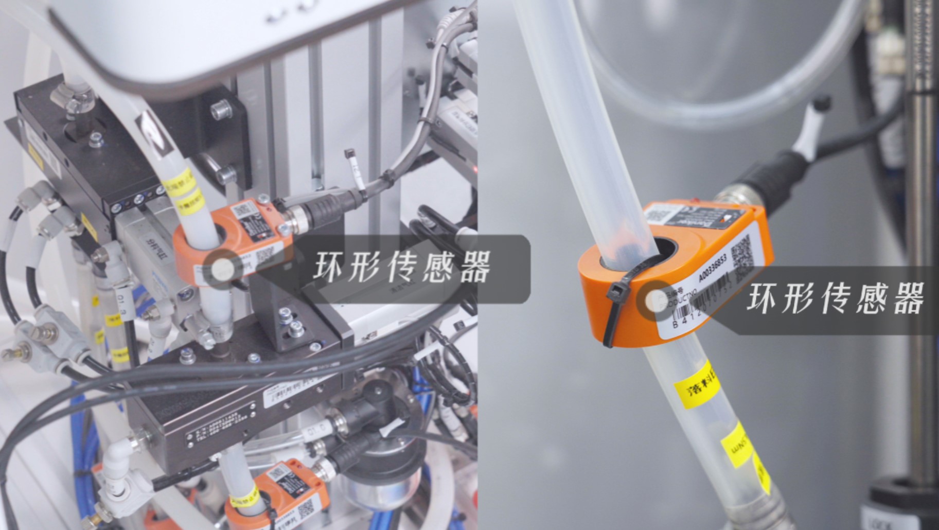
After the PLC sends a screw request signal, the feeder starts blowing the screw. Ring photoelectric sensors are installed at both ends of the blow tube (at the feeder outlet and the entrance of the tightening module). When a screw passes through, the sensor sends a “screw passed” signal back to the PLC. Only after receiving this signal does the PLC determine that the screw is in place and trigger the tightening module to proceed.
If the signal is not received within a set time, the PLC issues a “feeding anomaly alarm” to prompt timely troubleshooting. Additionally, a low-level sensor is installed at the bottom of the feeder hopper. When screws are insufficient, it triggers a replenishment signal and automatically links with the storage system to refill, preventing missed feeding due to late manual refilling.

2. Length Detection Module: Automatically Filter Out Non-Conforming Screws to Prevent Wrong Feeding
The core issue of wrong feeding is the inability to identify screws with abnormal specifications. This can be resolved by adding a length detection module during the feeding process.
Built-in modules offer a detection accuracy of ±1mm, while external modules offer ±1.5mm.
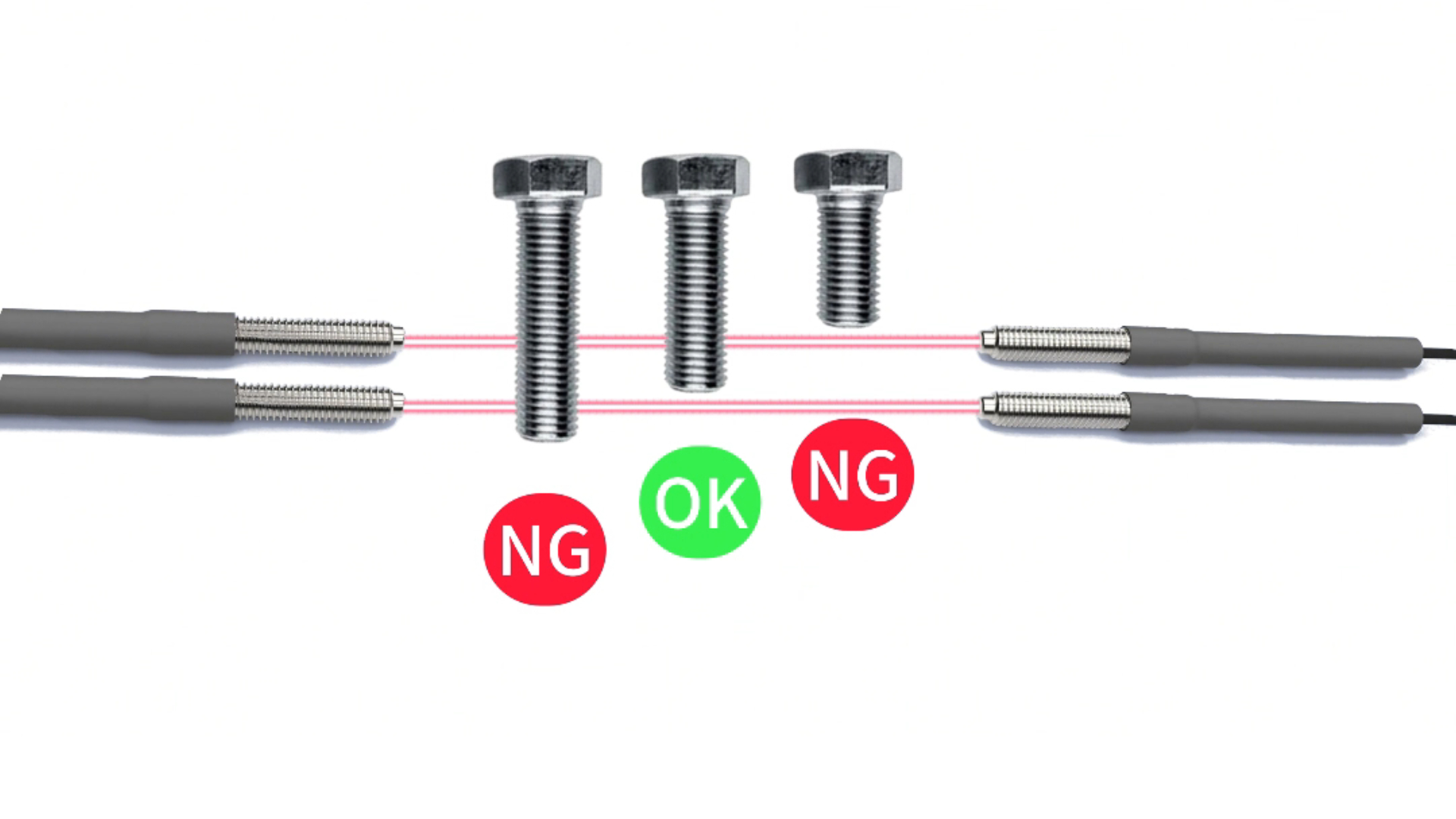
The principle involves using two sets of through-beam fiber optics to define an acceptable range. If the tail of the screw falls between the two beams (i.e., one beam is blocked), the screw is considered acceptable and continues to be transported.
If neither or both beams are blocked, the screw is deemed too short or too long, classified as non-conforming, and ejected into a reject bin via the NG channel.
Additionally, a QR code scanner can be installed at the feeder’s refill port. Only after scanning the correct screw QR code can the refill port be opened, preventing large-scale NG due to incorrect material feeding.

3. Feeding Efficiency Optimization: Rational Layout to Match Production Rhythm and Prevent Slow Feeding
The key to slow feeding is that the feeding speed cannot match the production line’s rhythm. This requires improvement from both parameter tuning and on-site layout.
First, ensure the feeder’s vibration frequency allows for continuous and stable feeding. For standard screws, the feeding speed should be ≥40 pcs/min.
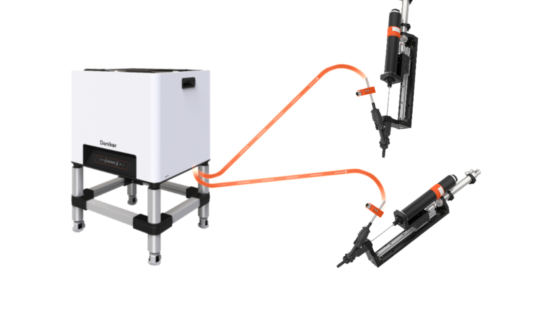
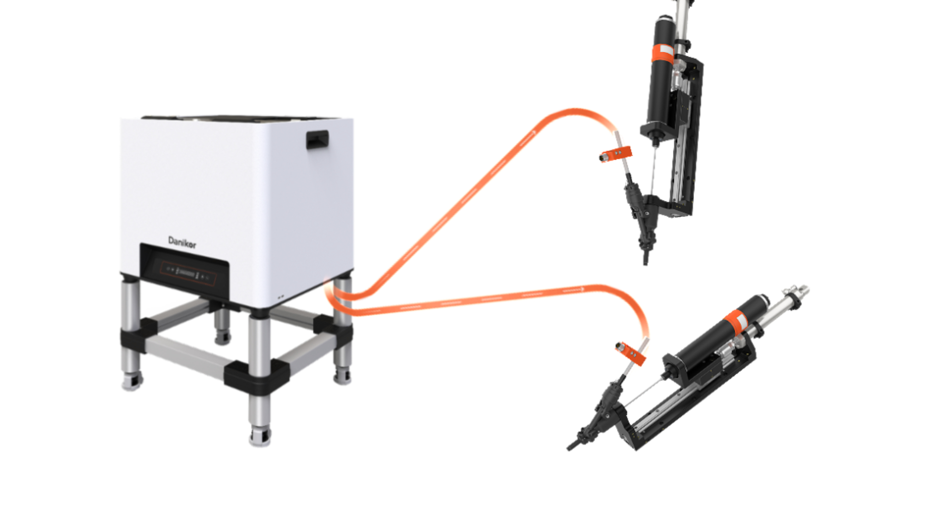
The layout of the blow tube should be optimized: while ensuring proper bend radius, the tube length should be minimized to avoid unnecessary detours.
Avoid overextending one feeder to multiple stations just to save costs, which may lead to insufficient supply. Instead, conduct cycle time matching tests to simulate the feeding frequency required by the target production line and ensure the feeder can keep up in real applications.


With the advancement of Industry 4.0, screw feeding machines will evolve toward intelligent systems, further enhancing adaptability and reliability, and becoming the “accurate feeding safeguard” of smart manufacturing production lines.


